THE VEHICLE PRESENTED HERE IS AN ELECTRIC CAR THAT DOES NOT
REQUIRE BATTERY RECHARGING
THE FOLLOWING RELATION DETERMINES THE AVERAGE DAILY RANGE OF
THIS VEHICLE
It alternately turns into two different entities:
1.
during parking it is an accelerator of the slow atmospheric city wind, much
larger than a car, oriented by a software, equipped with wind generators and
photovoltaic panels.
2.
during the motion is a car.
In
particular,
when
parked,
the
extended
front
conveyor
similar
to
a
"Venturi
tube",
through
wind
generators
placed
in
the
bottleneck,
is
able
to
absorb
part
of
the
energy
present
in
the
slow
atmospheric
wind
of
the
city
(and
solar
energy,
as
it
is
covered,
in
its
oblique
development,
from
photovoltaic
panels),
sufficient
to
allow
-
once
this
structure
has
been
transformed
into
a
car
-
to
cover
the
average
daily
distance
traveled
by
a
car
in
the city equal to about 30 km.
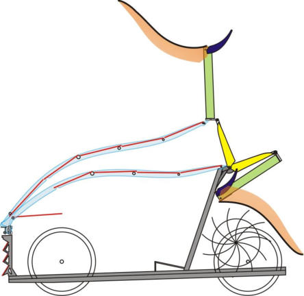
The
roof
of
such
a
car
is
sandwiched
with
two
overlapping
layers,
one
lower
and
one
upper.
The
bottom
layer
consists
of
the
roof
of
the
passenger
compartment.
The
upper
layer
is
hinged
at
the
front
and
therefore
able
to
rotate
by
lifting
the
back
due
to
the
effect
of
the
action
of
electromechanical
jacks.
This
element
-once
extracted-
with
oblique
surface,
low
anteriorly,
high
posteriorly,
constitutes
the
lower
ascending
end
of
the
said
"Venturi
tube".
On
the
rear
end,
so
raised,
are
placed
retractable
wind
generators.
Above
these
generators
is
placed
an
air
guide
element,
also
retractable,
which
constitutes
the
upper
descending
end
of
the
"Venturi
tube".
This
latter
element
is
large
in
size
and
equipped with valves that protect such a large structure from gusts of wind.
On
the
lower
oblique
end
said
and
on
part
of
the
upper
one
are
placed
photovoltaic
panels.
This
structure,
once
extracted,
has
an
overall
surface
area
much
larger
than
that
of
a car, while maintaining the longitudinal and transverse dimensions of a normal car.
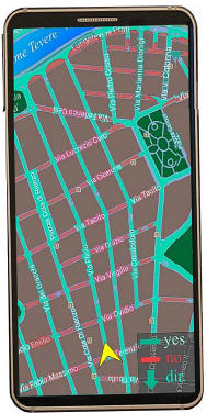
A
software-navigator,
downloading
the
weather
forecast
from
meteorology
websites,
indicates,
with
different
colors,
to
the
user,
on
the
map,
the
roads
where
to
park.
Typically,
the
wind,
in
the
city,
runs
parallel
to
the
streets,
not
being
able
to
cross
the
buildings
that
are
line
them,
and
runs
faster
along
those
streets
that
are
arranged
parallel
to
the
direction
of
the
atmospheric wind.
However,
a
city
is
an
aerodynamic
object
that
has
its
own
characteristics:
in
some
places
the
combination
of
the
shape
of
the
buildings
increases
the
speed
of
the
atmospheric
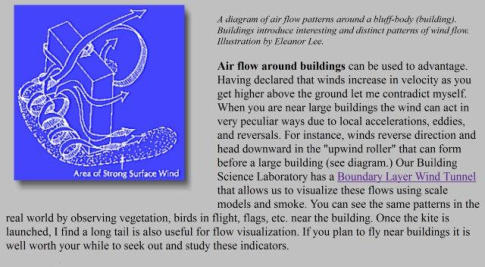
wind while in others decreases it (see box below).
To
optimize
the
performance
of
the
vehicle,
said
software
records,
using
sensors
put
on
the
car,
in
the
places
where
the
car
is
parked,
the
real
speed
of
the
wind
compared
to
the
atmospheric
wind
speed
of
a
determinate
direction.
In
a
subsequent
time,
the
software,
knowing
the
direction
of
the
atmospheric
wind,
may
indicate
to
the
user
the
sites
where
is
convenient
to
park
the
car,
in
a
way
weighted
with
the specific aerodynamics of the place.
The
parking
lots
that
line
the
streets
are
hit
by
direct
sunlight
for
a
time
that
depends
on
the
orientation
of
the
streets
themselves,
their
width
and
the
height
of
the
buildings that flank them, the trees.
Many
software-navigators
contain
data
on
the
layout
and
width
of
the
roads.
If
the
data
on
the
height
of
the
buildings
is
not
available,
which
would
make
the
shading
time
immediately
deductible,
with
sensors
placed
on
the
car
that
detect
the
difference
shade
/
sunlight,
said
software
records
the
time
in
which
the
places
where
the
user
usually
parks
receive direct light, learning the characteristics of the insolation.
The
software-navigator,
thus
determining
the
places
where
the
best
combined
productivity
of
the
wind
and
photovoltaic
system
of
the
car
will
occur,
indicates,
as
mentioned, with different colors, to the user, on the map, the roads where to park.
1
.
the
use
of
a
software,
as
described
above,
capable
of
determining
and
indicating
to
the
user
the
places
where
the
conditions
of
the
best
combined
productivity
of
the
wind
and
photovoltaic
plants
will
occur;
2
.
parking
in
the
streets
indicated
by
the
software.
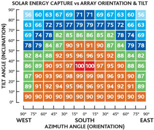
(A
moderate
deviation
from
the
direction
indicated
by
the
software
does
not
produce
a
significant
reduction
in
the
solar
energy
absorbed
-
see
diagram
on
the
right);
3
.
to
simplify
the
calculation,
the
wind
is
considered
as
blowing
from
random
direction,
that
is,
that
every
day
the
wind
has
the
equiprobability
to
blow
from
any
direction
(This
calculation
will
offer
lower
results
in
energy
terms
than
those
obtainable
in
those
cities
that
have
the
dominant
wind
of
prevailing
south-north
or
north-
south direction);
4
.
the
efficiency
of
the
conveyor
is
considered
to
be
85
%
(it
is
a
prudent
data
as
the
conveyor
has
an
angle
of
convergence
moderate,
such
as
to
reduce
friction
to a minimum);
5
.
For
the
calculation
of
the
photovoltaic
energy
actually
producible
by
the
vehicle
placed
in
a
city
environment,
characterized
by
the
presence
of
buildings,
trees,
and
other
objects
that
determine
the
existence
of
dynamic
shadows,
a
coefficient
was
considered
such
as
to
reduce
the
productivity
of
the
panels.
This
coefficient
has been identified in the measure of 75%.
The
measure
of
75%
is
a
conservative
value.
For
example,
if
you
park
near
the
south
end
of
a
large
square,
the
insolation
will
be
equal
to
100%,
not
being
reached
this
area
by
the
shadow
of
the
buildings,
that
are
located
on
the
opposite
side
of
the
square
and
therefore
the
profitability
of
the
car
panels,
in
this
case,
will
not
be
reduced
and
will
be
equal
to
that
of
equivalent
panels
placed
in
a
fixed
position
on
a
roof
of
a
building,
without
shadows.
If
you
park,
instead,
in
a
road
facing
south,
the
buildings
that
line
it
reduce,
with
their
shadows,
the
time
in
which
the
panels
receive
direct
light,
proportionally
to
their height and the width of the road.
However,
the
profitability
of
car
panels
compared
to
that
of
panels
of
equal
size
and
inclination
placed
on
a
roof,
is
not
reduced
proportionally
to
the
time
in
which
the
car
panels
are
shaded
by
the
buildings.
In
fact,
the
hours
of
greatest
productivity
of
the
fixed
panels
(whose
values
were
used
in
this
calculation
being
fixed
as
those
of
the
car
once
parked)
are
only
those
near
to
noon
and
therefore
the
shading
of
the
buildings,
which
does
not
occur
in
the
hours
near
to
noon,
does
not
react
in
an
important
way
on
the
measure
of
the
overall
energy
collected.
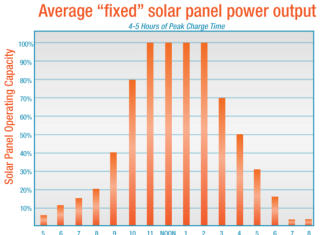
The
car,
in
fact,
in
the
few
hours
around
at
midday,
receives
anyway
the
100%,
or
an
extent
close
to
this
value,
of
the
"Peak
Charge
Time"
(see
graph
above)
that
is
the
moment
that
determines
the
substantial
profitability
of
the
fixed
panels.
In
the
hours
before
and
after
the
"Peak
Charge
Time",
which
still
offer
little
energy
even
to
panels
placed
on
a
roof
without
shadows,
the
car
panels,
while
collecting
less
energy,
will
continue
to
absorb
the
indirect
light,
reflected from the facades of the buildings.
Making
an
approximate
calculation,
using
the
scheme
above,
adding
the
values
of
percentage
points
as
the
amount
of
energy
absorbed,
in
5
hours
(from
10
am
to
2
pm)
during
the
"Peak
Charge
Time"
you
get
480
points
from
the
panels
placed
on
the
car
or
on
the
roof
of
the
building
indifferently.
The
remaining
hours
added
together
offer
255
points
to
the
panels
placed
the
roof
of
the
building,
while
the
car
goes
into
the
shade.
Imagining
that
diffused
light
makes
only
10%
of
direct
light,
the
car
achieves
from
diffused
light,
outside
of
"Peak
Charge
Time"
only
25.5
points
instead
of
255.
So
a
total
of
25.5
+
480
=
505.5
points
for
the
car
and
255
+
480
=
735
points
for
the
roof
of
the
building.
It
is
therefore
easy
to
deduce
that
in
this
situation
the
profitability
of
the
car
panels
is
still
68.77%
(=
505.5/735)
of
that
of
equivalent
panels
placed
on
the
roof of the building.
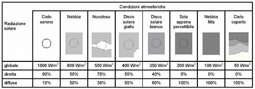
It
should
also
be
considered
that
the
data
used
to
determine
the
profitability
of
the
car's
photovoltaic
panels
are
aggregated
and
include
the
profitability
of
the
panels
on
cloudy
and
rainy
days
during
which
the
ratio
b
e
t
w
e
e
n
d
i
f
f
u
s
e
d
and
direct
light
is
d
i
f
f
e
r
e
n
t
,
(see
box
on
the
right).
T
h
e
r
e
f
o
r
e
,
a
value
of
75%
is
considered
plausible
for
the
coefficient
of
reduction
of
the
average
productivity
of the panels placed on the car.
As
mentioned,
75%
is
an
average
value
that
can
increase
or
decrease
in
relation to the width of the streets and the height of the buildings.
6.
It
is
considered
a
parking
time
and
therefore
of
operation
of
the
electricity
generation
system
equal
to
23
hours
for
the
wind
system
(assuming
the
use
of
the
car
on
average
for
1
hour
a
day)
and
24
hours
for
photovoltaic
power
system,
that
work
during
the
move
of
the
car,
(using
the
average
data
on
24
hours, which includes the non-productivity of the night hours);
7.
Cities
object
of
the
simulation:
Rome
and
London.
These
cities
were
chosen
as
a
reference
because
they
are
characterized
by
the
first
for
being
a
sunny
but
not
very
windy
city,
the
second
for
being
a
little
sunny
but
windy
city, in order to make the results of this analysis as general as possible.
8.
an
electrical
circuit
efficiency
of
90%
is
considered
in
such
a
way
as
to
take
into
account
the
energy
dispersed
in
the
various
electrical
conductors
by
the
Joule effect.
9.
the
use
of
photovoltaic
panels
(monocrystalline
type)
Peak
power:
0.218
KwP/m2
WIND SYSTEM
DATA
DESCRIPTION
VALUE
S
f
FRONT SECTION
Input of the
aerodynamic duct
FRONT UPPER CONVEYOR SECTION
1.50 m (width car m 1,60 -10 cm frame width
containing the roof-conveyor) 3.04 m (total height
from the ground to the upper end of the upper wing)
to which are subtracted 77 cm from the ground that
are aerodynamically "covered" by the car parked in
front, therefore 3.04 m) - 0.77 (from the ground to
the height of the influence aerodynamics of the car
parked in front) = 2.27 x 1 m, 50 = 3,405 sq.m.
S
cs
HIGHER CAUDAL
SECTION
(rear aerodynamic
conveyor)
SECTION OF REAR CONVEYOR OF THE
UPPER WIND GENERATORS
2.75
m
(upper
limit:
that
is,
the
high
end
of
the
rear
wing,
of
the
rear
duct
of
upper
fan)
minus
m
1.60
(lower
limit
of
rear
conveyor
of
upper
wind
generators)
=
m
1.15
*
1.50
(duct
width)
=
1.72
sq.
m
S
ci
LOWER CAUDAL
SECTION
(of the rear
aerodynamic
conveyor)
REAR CONVEYOR SECTION OF THE LOWER
RESITANCE-FAN
m 1.60 (upper limit of lower duct of resistance-fan)
minus m 0.70 (height of the aerodynamic wake
produced by the car behind parked, with the wind
blowing from behind) =
0,90 m (total height conveyor of rear resistance fan)
* m 1.5 rear fan duct width of rear resistance - fan =
1.35 sqm
S
l
SIDE SECTION
the side wind
generator system
contained into the
rims
(overall section)
25-inch wheels; (62 cm diameter channel, 58 cm
diameter propeller disc contained therein)
Area of the channels
62
cm
/
2
=
31cm
(radius)
x
31
2
x
π
3.14
=
0,
30
square
meters
(area
of
one
channel)
0,
30
square
meters * 2 =
0.6 sq.m.
(area of the two channels)
Area of the turbine
60
cm
-
2
cm
(clearance
between
turbine
and
circle)
= 58cm
(58cm/2)
2
x
π
≈
0,26
mq
(area
of
one
turbine)
0,26x2
=
mq
0,528
(area
of
the
two
turbines,
(area
of
the
two
turbines
exposed
to
the
crosswind,
considering
that
depending
on
the
direction
from
which
the
wind
blows,
the
two
wheels
on
the
right
or left side of the car are exposed)
VV
L
Average wind speed in
London:
5m/s
Source: Map published by the National Rice
Laboratory achievable to the address:
http://www.wasp.dk/WindAtlas/EuropeanWindAtla
VV
R
Average wind speed in
Rome 3.5m/s
3,5m/s
Source: Mappublished by the Riso National
Laboratory reached at: http://www.wasp.dk/Wind
Atlas/EuropeanWindAtlas

PHOTOVOLTAIC SYSTEM
PANELS (monocrystaline type) Peak Power: 0,21 KwP/h m2
DATA
TILT
PANELS DIMENSIONS
SURFACE sq. m
Panel 1
51°
cm 52 x 150
0,78
Panel 2
31°
cm 42 x 150
0,63
Panel 3
14°
cm 42 x 150
0,63
Panel 4
12°
cm 42 x 150
0,63
Panel 5
25°
cm 42 x 150
0,63
Panel 6
35°
cm 37 x 150
0,55
Panel 7
55°
cm 10 x 150
0,15
Panel 8
55°
cm 10 x 150
0,15
Panel 9
55°
cm 10 x 150
0,15
Panel 10
35°
cm 48 x 29
0,14
Panel 11
35°
cm 48 x 29
0,14
TOTAL
4,58 mq

EFFICIENCY OF THE PLANTS
DATA
DESCRIPTION
VALUE
SOURCE
CA
e
Aerodynamic
duct
85%
In the absence of experimental data, the
efficiency of the conveyor was considered to
be 85% (this is a prudent figure because this
conveyor has an not accentuated convergence
angle).
PE
e
Upper wind
turbine with lift
blades
(horizontal axis)
45%
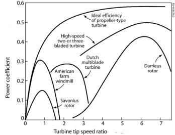
Efficiency characteristic of this type of
turbine. This value has been deduced from the
graph shown here, available on the website of
the Canadian University of Calgary
http://www.ucalgary.ca/
TI
e
lower turbine
with resistance
blades
(horizontal axis)
30%
Characteristic efficiency of this type of turbine
(green above)
GC
e
Permanent
magnet power
generator
93%
Plate data of the generator type 210 of the soc.
PMGL link: http://www.pmgenerators.com;
http://www.pmgenerators.com/products/series-
hybrid-alternators
PFM
e
"Monocrystalline
photovoltaic
panels”
21%
efficiency
kW/p
ratio:
218w/sq
m)
C
o
Coefficient
reduction power
photovoltaic
panels for
shading
75%
For
the
calculation
of
the
photovoltaic
energy
actually
producible
by
the
vehicle
placed
in
a
city
environment,
characterized
by
buildings,
trees,
and
other
objects
that
determine
the
presence
of
shadows,
a
coefficient
was
considered
such
as
to
reduce
the
productivity
of
the
panels.
This
coefficient
has
been
set
at
75% for the reasons given above.
RC
e
Charge controller
(charger)
98%
Plate data of: Steca model: Solarix MPPT
2010, indicates 98% conversion efficiency
link: http://www.steca.com/index.php?Steca-
Solarix-MPPT-en
B
e
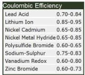
Lithium battery
90%
Coulombic
efficiency:
(for
a
rechargeable
battery
it
is
the
fraction
of
the
electrical
charge
stored
during
battery
charging
that
is
recoverable
during
use).
l
i
n
k
:
h
t
t
p
:
/
/
w
w
w
.
d
i
r
a
c
d
e
l
t
a
.
c
o
.
u
k
/
s
c
i
e
n
c
e
/
s
o
u
r
c
e
/
c
/
o
/
c
o
u
l
o
m
b
i
c
%
2
0
e
f
f
i
c
i
e
n
c
y
/
s
o
u
r
c
e
.
h
t
m
l
#
.
VRh4vI7LLiM
ECE
e
Electrical circuit
efficiency
Energy
dissipated in the
electrical
components of
the circuit
90%
Coefficient
assumed
in
such
a
way
as
to
take
into
account
the
energy
dissipated
in
the
electrical components due to the Joule effect.
M
e
Electric motor
for automotive
93%
Plate data for Enrmax 207 series engines
indicate an efficiency of between 93% and
98%. (Directive 2005/32/EC imposes a
minimum efficiency for electric motors of
89.5%. This means that any engine with lower
efficiency is illegal).

The
calculations
performed
for
the
determination
of
the
range
of
the
vehicle
in
question
are
indicated
in
the
attached
Excel
files
with
the
name
"Rome"
and
"London"
that you can found in this site.
The
nature
of
the
data
entered
in
them
and
their
source
are
set
out
in
the
previous pages of this document.
Excel
files
contain
the
following
named
pages,
in
order:
"Main";
"Aggregation";
"Wind
farm
summary";
"Frontal
Wind";
"Upper
rear
wind";
"Lower
rear
wind";
"Lateral wind"; "Photovoltaic",
In particular:
1
.
the
"Main"
page,
accepting
as
input
the
value
of
the
average
energy
produced
by
the
car
resulting
from
the
best
combination
of
the
photovoltaic
and
wind
power
systems,
and
considering
the
various
efficiency
losses
indicated
above,
determines
the
average
autonomy
of
the
car
expressed
in
kilometres
per
day;
2
.
the
"Aggregation"
page
aims
to
estimate
the
total
energy
that
can
be
absorbed
by
the
car
by
combining
the
energy
produced
by
the
photovoltaic
system and the wind farm.
To this end, it acquires as input:
a
)
the
value
of
the
wind
energy
on
average
that
can
be
produced
by
the
car
in
a
year
considering
the
various
possible
orientations
of
the
parked
car,
compared
to
the
wind
direction
with
intervals
of
5
°
(in
particular,
-180
°
for
the
wind
coming
from
the
rear,
-90
°
for
the
wind
coming
from
the
left,
0
°
for
the
wind
coming
from
the
front,
etc.)
The
calculation
of
these
values
will
be
better
detailed
on
the
page
"Wind
summary";
b
)
the
value
of
the
photovoltaic
energy
that
can
be
produced
on
average
by
the
parked
car,
in
a
year,
considering
the
various
possible
orientations
of
the
car
with
respect
to
the
south
(orientation
that
guarantees
maximum
manufacturability),
with
intervals
of
5
°
(in
particular,
-180
°
for
the
car
oriented
to
the
north,
-90
°
for
the
car
oriented
to
the
east,
0
°
for
the
car
oriented
to
the
south,
etc.).
The
calculation
of
these
values
will
be
better
detailed
on
the
"photovoltaic"
page.
Clearly
you
will
not
get
the
maximum
productivity
of
both
systems
at
the
same
time,
as
the
photovoltaic
system
provides
its
maximum
productivity
when
the
car
is
oriented
to
the
south,
while
the
wind
generator
system
provides
its
maximum
productivity when the machine is oriented against the wind.
le able to maximize the overall productivity of the two plants.
The
"Aggregation"
page
considers
all
the
possible
directions
of
origin
of
the
wind
(with
steps
of
5
°)
and
calculates
for
each
the
value
of
the
maximum
energy
that
can
be
produced
overall
by
identifying
the
compromise
in
the
simultaneous
working
condition
of
the
two
systems
that
allows
to
obtain
the
maximum
overall
energy
(that
is, it simulates the operation of the software described above).
As
specified
in
the
chapter
on
the
hypotheses
underlying
the
simulation,
a
condition
of
equiprobability
of
the
direction
of
origin
of
the
wind
was
considered,
therefore
devoid
of
dominance
(see
point
3
of
this
doc.),
and
the
energy
that
can
be
produced
by
the
car
was
therefore
calculated,
as
an
average
on
an
annual
basis
of
the
values of overall producibility, in the sense described above, of the two systems;
3).
the
page
"Wind
Summary"
shows
the
value
of
the
energy
output
from
all
wind
systems
of
the
car
(front
generator,
rear
top
and
bottom,
generators
intubated
in
circles),
with
different
wind
directions
respect
to
the
parked
car.
For
this
purpose,
acquires as input the values of the pages listed below:
1
.
Frontal wind generator
2
.
rear top wind generator;
3
.
lower rear wind generator;
4
.
side
wind
generator,
and
combines
them
by
performing
simple
trigonometric calculations inserted into the spreadsheet of the Excel file.
_________________________
1
.
the
"Frontal
Wind
generator"
page
acquires
as
input
the
data
relating
to
the
average
wind
speed
in
the
simulated
city
and
the
characteristic
data
of
the
frontal
wind
system
detailed
in
the
initial
section
of
this
document,
to
calculate
the
average
energy
that
can
be
produced
by
the
car
oriented
with
the
wind
in
front;
2
.
the
page
"
rear
top
wind
generator"
acquires
as
input
the
data
relating
to
the
average
wind
speed
in
the
simulated
city
and
the
characteristic
data
of
the
upper
rear
wind
system
detailed
in
the
initial
section
of
this
document
to
calculate
the
average
energy
that
can
be
produced
by
the
car
oriented
with
the
wind coming from behind and received at the rear by the upper wind generators;
3
.
the
page
"
lower
rear
Wind
generator
"
acquires
as
input
the
data
relating
to
the
average
wind
speed
in
the
simulated
city
and
the
characteristic
data
of
the
lower
rear
wind
system
detailed
in
the
initial
section
of
this
document
to
calculate
the
average
energy
that
can
be
produced
by
the
car
oriented
with
the
wind
coming
from
behind
and
received
from
the
lower
rear
wind generator;
4
.
the
page
"Lateral
wind"
acquires
as
input
the
data
relating
to
the
average
wind
speed
in
the
simulated
city
and
the
characteristic
data
of
the
lateral
wind
system
detailed
in
the
initial
section
of
this
document
to
calculate
the
average energy that can be produced by the car oriented with the side wind;
5
.
the
"Photovoltaic"
page
contains
the
data
extracted
from
the
simulator
made
available
by
the
European
Community
accessible
at
the
web
address:
http://re.jrc.ec.europa.eu/pvgis/apps4/pvest.php
.
In
particular,
for
each
different
inclination
of
each
photovoltaic
panel
with
respect
to
the
horizon,
have
been
included,
in
the
table,
the
data
of
productivity
to
the
vary
of
the
orientation
of
the
PV
panel
with
respect
to
the
south,
extracted
from
the
simulator
shown
above,
has
been
inserted
in
the
table.
The
overall
productivity
of
the
photovoltaic
system
for
each
possible
orientation
with
respect
to
the
south
is
calculated by adding these values.
The
above
simulations
were
performed
considering
the
data
of
productivity
of
photovoltaic
panels
and
the
average
wind
speed
relative
to
the
cities
of
Rome
and
London,
getting
an
average
producibility
of
around
2.7
kWh
per
day
for
the
first
city
and 2,8 kWh for the second.
CONCLUSIONS
Considering
that
a
standard
quadricycle
reaches,
with
5
hp
(limited
by
law),
45
km
/
h
(this
value
also
limited
by
law),
and
considering
the
constructive
similarity
between
these
quadricycles
available
on
the
market
and
the
vehicle
in
question,
it
is
possible
to
estimate
the
distance
that
this
car
can
travel
on
average
in
the
city
of
Rome
and
London,
respectively:
33km
and
34km
a
day.
In
this
simulation,
the
energy
saving
advantage
(e.g.
the
decrease
in
rolling
friction)
that
the
vehicle
in
question
derives
from
the
aerodynamic
rims
and
large
diameter
high-pressure
tyres
from
which
it
is
equipped
compared
to
the
normal
tyres
of
the
standard
quadricycle
under
consideration was not taken into account.



© Copyright, AUTOMOBILI CUNICO tutti i diritti riservati

CALCULATION OF THE RANGE OF THE VEHICLE:
AUTOMOBILI CUNICO


